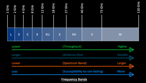
We often hear about beamforming from the trade press, on podcasts, and elsewhere, but what is it and why should you care? To get to understanding beamforming, consider how it uses the precise phase shifting of antenna array elements to create a very narrow, specifically directed beam. This narrow beam significantly increases the gain for the intended receiver and simultaneously reduces interference for other nearby devices. Beamforming proves useful in sub-6 GHz applications, but it truly shines in the millimeter-wave bands where it effectively counters the severe free space path loss (FSPL) and oxygen absorption that occur at 60 GHz. Beamforming can occur in three different ways:
- Analog beamforming
- Digital beamforming
- Hybrid beamforming
A high-level overview of these different techniques will initiate a discussion on MIMO (multiple input, multiple output) technology, a form of spatial multiplexing that leverages beamforming technology.
Any radio system comprises two parts: the digital baseband modem and the RF subsystem (RFIC + antenna array), each playing a role in understanding beamforming.

Analog Beamforming
In analog beamforming, the digital baseband sends a single data stream through a radio chain that creates an analog signal in the millimeter-wave band. This signal then passes through an array of phase shifters to form a very narrow beam with tremendous gain. Depending on the design, you might observe up to 30 dBi (decibels relative to isotropic) of antenna gain from a large array. These arrays utilize patch antenna elements, each about 2 millimeters square, when operating at 60 GHz. An array can contain up to 256 of these elements. By precisely adjusting the phase (and amplitude) of each patch antenna element, you can focus a very narrow beam in a very specific direction. Since regulations limit power, as defined by EIRP (Effective Isotropic Radiated Power), the narrower the beam, the greater the gain for the intended receiver.
Airvine employs analog beamforming to create a very high-gain antenna in its groundbreaking WaveTunnel system.
Digital Beamforming
In this approach, the digital baseband performs all phase shifting. This allows for incredibly precise beams and nulls (absence of RF energy), but it doesn’t scale well because you need a full radio chain for each antenna element. A typical implementation might involve 16 data streams running through 16 radio chains into 16 antenna elements. Digital beamforming supports multi-user MIMO, enabling communication with multiple users over the same RF channel simultaneously. To reduce interference, MU-MIMO directs a very narrow beam at each intended user, with nulls aimed at everyone else. This situation brings us back to beamforming, most effectively applied in the millimeter-wave bands with many antenna elements. Implementing this in the digital domain proves costly and power-intensive. A compelling alternative would be to combine the large arrays possible with analog beamforming with the MU-MIMO capabilities of digital beamforming, leading to hybrid beamforming.
Hybrid Beamforming
People often refer to this combination of multi-user MIMO and analog beamforming as MASSIVE MIMO. Each beam delivers maximum energy to the intended user while generating nulls aimed at all other users. As users move around in the coverage area, the digital baseband recalculates all the phase shifts to maintain user satisfaction. The advantage of operating in the V-band (60 GHz) is that a large array of antenna elements fits easily on a PCB smaller than 20 cm². This approach suits access networks deployed in heavily congested areas like stadiums, city centers, convention centers, and airports, where it’s crucial to connect large numbers of people in confined spaces.
Receive Beamforming
Most discussions of beamforming focus on the transmit side, but we must also consider the receive side. The system phase shifts the RF signal across all transmit patch antenna elements and must also phase-shift it across the receive side. This step aims to align all receive signals and bring them into phase so that they can combine into a strong signal. An example clarifies this: if the transmitter is to the left of the receiver, then the patch antenna elements on the left side of the receiver’s PCB will receive the signal before those on the right side. We cannot successfully combine these signals until they are all in phase.
Side Lobes
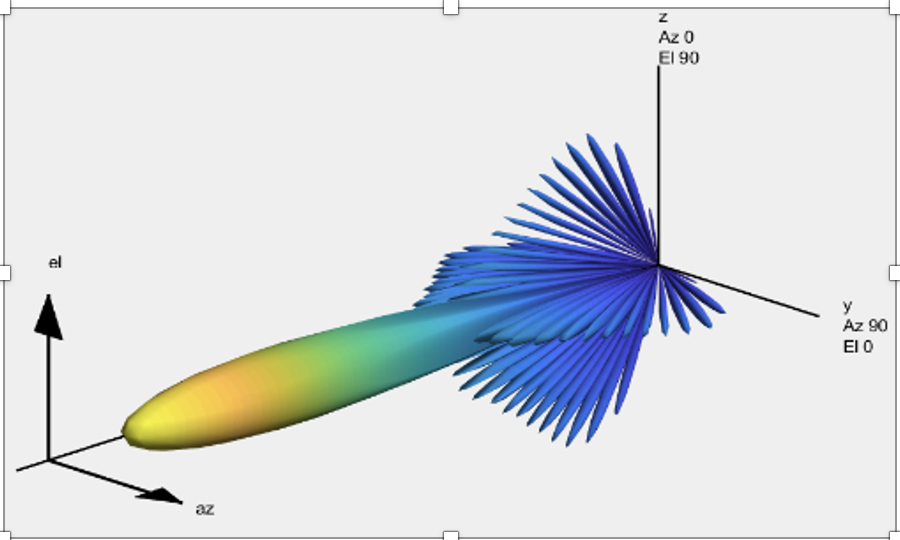 The beamforming process inevitably creates side lobes of radio energy. Some extraneous RF energy will always exist outside the primary beam. The goal is to minimize this energy as much as possible. These lobes appear as interference to other users in the operating area and divert energy from the primary beam directed at the intended user. A common objective in any millimeter-wave design is to achieve side lobe suppression of at least 20 dB (see figure below). This suppression means that side lobe traffic is at least 100 times weaker than the primary beam.
Understanding Beamforming
Beamforming technology is ideally suited for the millimeter-wave bands as it can fit into a very small enclosure, easily overcomes free space path loss, and limits co-channel interference. Three major beamforming approaches can be used, with the analog implementations being best suited to backbone applications in the V-band because of their ability to build large arrays that create narrow beams at very high gain. All of which is perfect for punching through walls @ 60 GHz.
Need more info to get better at understanding beamforming? We’re experts.
Originally Posted on July 5, 2021 by Steve Hratko